BPF
Band Pass filters allow a specified range of frequencies pass through the circuit while limiting the impact of signals below or above the chosen frequency range.
The Calculations⌗
Both high- and low-pass filters use the same math to determine their effective frequency. The orientation of the passive components (Resistor and Capacitor in this example here) is what dictates whether high- or low-pass filtering is achieved.
The effective function for RC filters is:
$(\omega = \dfrac{1}{2\pi RC} \approx \dfrac{1}{6.28 RC})$
Low-Pass Filters⌗
First, let’s take a look at LPFs, or Low-Pass Filters. LPFs form a floor of signal frequency that it will allow through. In the case of AC circuits, the resistor creates impedance, assuming fixed current and resistor value in Ohms, this will modulate the RMS voltage of the waveform (reducing it’s amplitude). This will oscillate with the reactance provided by the capacitor that couples the resistor line to ground.
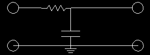
This creates a situation where the amplitude is greatly reduced where the circuit is not resonant due to the capacitor allowing a path to ground. More or less when the capacitor is “full” the signal has a path to the output line at the top right of the circuit. When the capacitor is draining it allows a path to ground where the signal is cancelled against the other output lead.
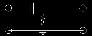
High-Pass Filters⌗
On the opposite end of the spectrum (ha!) we get the High-Pass Filter. This functions in the opposite way, where the capacitor is used to create resonance before the resistor is used to reduce the output. In each case, the resistor is creating reactance that reduces the signal at a range of frequencies, but the operative function is that it allows the frequencies within the resonance of the filters to pass through.
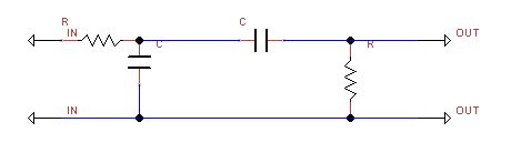
Putting it all together!⌗
If we want to make a radio with a specific frequency range, we can use these filters together to let a whole range of frequencies (or band in RF parlance) through the filter. Now, it would be possible (and in some cases necessary) to have two separate filters in sequence. This takes the output of the first filter (traditionally the Low-Pass Filter), and sets it as the input of the second filter (High-Pass Filter). At the end, we have an output where the non-desireable frequencies are attenuated and the desireable frequencies are more pronounced.
In practice, this is effectively what the circuit does, but the two are connected directly together in a Band-Pass Filter (BPF).